

-
Welcome to Tundras.com!
You are currently viewing as a guest! To get full-access, you need to register for a FREE account.
As a registered member, you’ll be able to:- Participate in all Tundra discussion topics
- Transfer over your build thread from a different forum to this one
- Communicate privately with other Tundra owners from around the world
- Post your own photos in our Members Gallery
- Access all special features of the site
 Relay mounting ideas
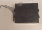 Hyperflashing Turn Signal Fix
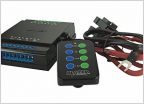 LED revers light pods install
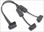 OBD 2 Port Splitter
 Which gauge wire should I use?
 12 Gauge 2 wire with PVC coat/jacket
Question(s) about Step-Down Butt Connector Splice
Discussion in 'Electrical' started by TnPlowboy, May 7, 2025.


