

-
Welcome to Tundras.com!
You are currently viewing as a guest! To get full-access, you need to register for a FREE account.
As a registered member, you’ll be able to:- Participate in all Tundra discussion topics
- Transfer over your build thread from a different forum to this one
- Communicate privately with other Tundra owners from around the world
- Post your own photos in our Members Gallery
- Access all special features of the site
 Looking at the TRD CAI
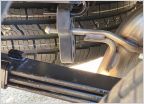 TRD dual exhaust leveling
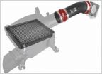 AFE super stock intake system
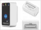 Code reader for 2015 Tundra
 Toyota techstream wont read data list
 SABM Review
General Supercharger Thread
Discussion in 'Performance and Tuning' started by snivilous, Mar 18, 2021.
Page 360 of 904
Page 360 of 904


