

-
Welcome to Tundras.com!
You are currently viewing as a guest! To get full-access, you need to register for a FREE account.
As a registered member, you’ll be able to:- Participate in all Tundra discussion topics
- Transfer over your build thread from a different forum to this one
- Communicate privately with other Tundra owners from around the world
- Post your own photos in our Members Gallery
- Access all special features of the site
 Air bag helper springs
 Old Man Emu Springs 2884 vs 2885
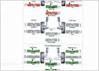 Alignment question
 2018 Tundra - with 3/1 Ready Lift and Tires
 Questions about 5100s, leveling and 1" lift
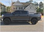 3/1 Leveling Kit
Bilstein 6112 DIY Install
Discussion in 'Suspension' started by equin, Aug 14, 2018.


