

-
Welcome to Tundras.com!
You are currently viewing as a guest! To get full-access, you need to register for a FREE account.
As a registered member, you’ll be able to:- Participate in all Tundra discussion topics
- Transfer over your build thread from a different forum to this one
- Communicate privately with other Tundra owners from around the world
- Post your own photos in our Members Gallery
- Access all special features of the site
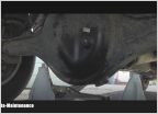 2008 Toyota Tundra Rear Differential Oil Change
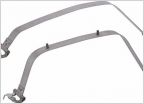 Fuel tank bracket
 Adding turn signal mirrors 2nd gen
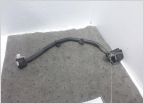 Looking for a new or used (not upgrade) plug n play direct bolt on replacement backup camera
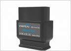 2011 Tundra Crew Cab 197,000 miles
2nd gen cluster
Discussion in '2nd Gen Tundras (2007-2013)' started by TundraCarter, Jan 31, 2022.
Page 12 of 16
Page 12 of 16
Products Discussed in


