

-
Welcome to Tundras.com!
You are currently viewing as a guest! To get full-access, you need to register for a FREE account.
As a registered member, you’ll be able to:- Participate in all Tundra discussion topics
- Transfer over your build thread from a different forum to this one
- Communicate privately with other Tundra owners from around the world
- Post your own photos in our Members Gallery
- Access all special features of the site
 Replacing a Topper Rear Window With Plexiglass/Acrylic
 Two easy shock questions
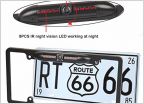 Backup camera
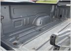 Rubber bed mat for double cab 1st gen tundra?
 Ditch lights and mounting brackets
AMP Powersteps on FGT Double Cab
Discussion in '1st Gen Tundras (2000-2006)' started by Tohopko, Mar 7, 2020.
Page 1 of 2
Page 1 of 2

