-
Welcome to Tundras.com!
You are currently viewing as a guest! To get full-access, you need to register for a FREE account.
As a registered member, you’ll be able to:- Participate in all Tundra discussion topics
- Transfer over your build thread from a different forum to this one
- Communicate privately with other Tundra owners from around the world
- Post your own photos in our Members Gallery
- Access all special features of the site
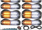 "OEM" or "Premium/upgraded OEM" strobes?
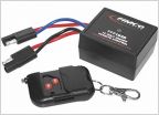 Can I have 2 switches power 1 lightbar?
 Swapping to Spyder Headlights
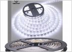 Wireless (cheap) LED lights for bed?
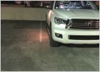 Tail light bulb replacement
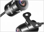 Front Camera Install
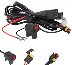
Custom Power Distribution Circuit with Switches and Relays
Discussion in 'Lighting' started by prodigalson84, Apr 29, 2020.