1. Welcome to Tundras.com!

    You are currently viewing as a guest! To get full-access, you need to register for a FREE account.

    As a registered member, you’ll be able to:
    • Participate in all Tundra discussion topics
    • Transfer over your build thread from a different forum to this one
    • Communicate privately with other Tundra owners from around the world
    • Post your own photos in our Members Gallery
    • Access all special features of the site

Re-purposing from rear of the integration relay/fuse box

Discussion in '1st Gen Tundras (2000-2006)' started by shifty`, Mar 23, 2022.

  1. Mar 23, 2022 at 6:25 AM
    #1
    shifty`

    shifty` [OP] Just like witches at black masses

    Joined:
    Jun 20, 2020
    Member:
    #48239
    Messages:
    28,362
    ATL
    Vehicle:
    '06 AC Limited V8/4WD
    (see signature for truck info)
    Curious, since I'm still probing around for possible plug-and-play solutions to get a clean, fused, no add-a-circuit source for ACC-PWR + ALWAYS-ON + GRND to the roof in AC/RC trucks ... (there's always-on already, and ground, but no ACC power)

    Has anyone ever tried looking at a pinout of the back of the integration relay, and using it for a similar purpose? I looked at my '06 AC EWD and I figured out where all the connectors are listed, but trying to make sense of (A) which place I'd want to plug into in the rear to steal my two hot sources and a ground, plus (B) which fuse each of these bulkheads relates to which fuse, and (C) which pins I'd tap off of ... that's what's got my eyes crossing. I'd need to take some Adderal to get enough focus to figure it out.

    I guess I need to start by snapping a pic of the rear of mine. This isn't mine pictured, obviously....

    Selfishly tagging @BubbaW for his opinion here.


    upload_2022-3-23_9-21-43.jpg
     
  2. Mar 23, 2022 at 7:17 AM
    #2
    BubbaW

    BubbaW Blessed 2 B above Ground

    Joined:
    Aug 19, 2019
    Member:
    #34845
    Messages:
    3,756
    First Name:
    Bubba
    Where Eagles Nest
    Vehicle:
    04 DC LTD 4X4 4.7 V8
    T150 Lover
    Since you have the 06 EWD, you're a step closer. If you downloaded from @RainMan_PNW EWD downloads for 06, it will be in PT 1 download, in particular the Relay Locations. The below is without DRL equipped, page 26. If you are with DRL, it would be page 30. I would have to re-read what you are attempting to offer further comments but my initial thought, if you're wishing to tap into back side, whether Integration or Fuse panel, I would be looking at tapping 15A ACC.

    Relay Locations.jpg

    15A ACC.jpg
     
  3. Mar 23, 2022 at 8:01 AM
    #3
    shifty`

    shifty` [OP] Just like witches at black masses

    Joined:
    Jun 20, 2020
    Member:
    #48239
    Messages:
    28,362
    ATL
    Vehicle:
    '06 AC Limited V8/4WD
    (see signature for truck info)
    Actually, you just gave me an idea. I was originally attacking this from the perspective of, "Hey, what if I see one of those ports on the back of the fuse/integration panel are empty, get the right empty connector, then pin it with three color-coded wires and run it up to the overhead console?!"

    I don't know why it didn't dawn on me until you posted those pics but the damn roof wire harness is right here. I'm going to look at the pinout for 1-7 on the integration relay side to see if the integration relay box is outputting ACC power to any of those 8 pins but OEM just didn't put a wire there. I have a factory DC harness already, which has all the necessary wires to pin in. But in reading the EWD, it looked like it was teeing off behind the gauge cluster. It just didn't click the roof harness would be plugged directly into the back of this integration relay.

    upload_2022-3-23_10-58-21.jpg
     
  4. Mar 23, 2022 at 6:22 PM
    #4
    RainMan_PNW

    RainMan_PNW "Oz" SSEM #82 RGBA #4 Unofficial Forum Treasurer Vendor?

    Joined:
    Oct 27, 2020
    Member:
    #54134
    Messages:
    16,766
    Gender:
    Male
    First Name:
    Casey
    Clark County, WA
    Vehicle:
    2021 Lunar Rock TRD Pro CM
    Check the build link in my signature.
    Start by searching the PDF for that connector name (1A) and you might be able to narrow down each different location where a wire hits that connector. There are only 7 of them so that can’t be too deep to dig.

    alternately, start with the connector in the overhead and work backwards.
     
    shifty`[QUOTED][OP] likes this.
  5. Mar 26, 2022 at 12:44 PM
    #5
    shifty`

    shifty` [OP] Just like witches at black masses

    Joined:
    Jun 20, 2020
    Member:
    #48239
    Messages:
    28,362
    ATL
    Vehicle:
    '06 AC Limited V8/4WD
    (see signature for truck info)
    Second thought. I can't even see if there are any free ports on the back, and it wasn't totally clear how to get easy access.

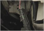
    I was able to dig in enough to get a shot of the 1A connector so I could at least see how many wires it has pinned, what color they are, then dig through the EWD to see what each wire's purpose.

    I'd prefer to pull the fusebox/integration panel out and run a DMM across the 1A pins on the box to see what's powered, because it looks like the EWD only is only going to show wires that are used in the connector, versus the full pin-out of the connector on the part side.

    Anyway, took a pic for posterity. Maybe another '06 Access Cab owner will benefit from having a pic of the connector. I'll need to go back down and see whether that 2nd blue wire has a stripe. Right now, it looks like all 8 wires may be pinned:

    - Black
    - Black/Yellow stripe
    - Green
    - Green/Black stripe
    - Green/Yellow stripe
    - Red/white stripe
    - Blue
    - Blue/Yellow stripe


    upload_2022-3-26_15-40-24.jpg
     
  6. Mar 26, 2022 at 12:57 PM
    #6
    shifty`

    shifty` [OP] Just like witches at black masses

    Joined:
    Jun 20, 2020
    Member:
    #48239
    Messages:
    28,362
    ATL
    Vehicle:
    '06 AC Limited V8/4WD
    (see signature for truck info)
    Tracing the (1A) roof wire harness on AC and RC trucks. Looks like it heads out of the back of the box, up the A pillar, and some of it tees of to connector IC2 which I believe is behind the instrument cluster. I'm 99% there's an ACC power lead that goes over to IC2, but doesn't go up to the roof. I remember looking that up prior.

    upload_2022-3-26_15-57-14.jpg
     
  7. Mar 26, 2022 at 1:03 PM
    #7
    shifty`

    shifty` [OP] Just like witches at black masses

    Joined:
    Jun 20, 2020
    Member:
    #48239
    Messages:
    28,362
    ATL
    Vehicle:
    '06 AC Limited V8/4WD
    (see signature for truck info)
    And once it gets up to the roof, for AC only, the layout. Need to check to see what color wires are at the initial fork above the driver side visor. Will try to find a BJ while I'm in there, since it's listed in the manual.

    upload_2022-3-26_16-3-4.jpg
     
  8. Mar 28, 2022 at 1:16 PM
    #8
    shifty`

    shifty` [OP] Just like witches at black masses

    Joined:
    Jun 20, 2020
    Member:
    #48239
    Messages:
    28,362
    ATL
    Vehicle:
    '06 AC Limited V8/4WD
    (see signature for truck info)
    So I started to consult EWD parts 1 and 2 against each other to come up with the following. Dumping this info as it relates to the Access Cab picture from EWD Part 1 below, in case it helps anyone, and for sake of subject documentation. I didn't spend the hour digging this BS up to forget it again. I swore I already did this once before and posted it.

    Sadly, while I27 shows as being part of the roof wire for my truck, I can't find its black 7-pin harness (with 2 wires, 5 empty) tucked away anywhere in my headliner. If it were, this would be a no-brainer, I could just tap its ACC power and ground, then fetch constant power off the dome light to build what I need.

    Interestingly, looking at my picture in reply # 5, I see a wire that's black with yellow stripe, just above the red wire, so I think it may actually be in the harness at the junction/fuse box (1A connector also seen in reply # 5)

    Since I'm having an impossible time trying to find any reasonably good pinout of connector 1A in reply # 5 above I opted to take things in reverse, the following connectors are documented for AC roof in EWD Part 1.

    Note: You can find the connector sample in EWD Part 1 by spacing the letter/number, i.e. search for "V 6" not "V6"
    Note: You can find the wiring flow sample in EWD Part 2 by spacing the letter/number, i.e. search for "V 6" not "V6"

    V6: "Vanity Light LH" => For Vanity/Visor light driver side
    Pin 1: BLK/WHT - ?? (from door switch?)
    Pin 2: BLU/YLW - ?? (from door switch?)

    I27: "Inner Mirror" => For dimming rear view mirror (if harness equipped)
    Pin 6: WHT/BLK - GND
    Pin 7: BLK/YLW - PWR (via 10A guage)

    P8: "Personal Light" => For Map light/Overhead console
    Pin 1: WHT/BLK - GND
    Pin 2: BLK/WHT - ?? (from door switch?)
    Pin 3: BLU/YLW - ?? (from door switch?)

    V7: "Vanity Light RH" => For sun visor light passenger side
    Pin 1: BLK/WHT - ?? (from door switch?)
    Pin 2: BLU/YLW - ?? (from door switch?)

    I26: "Interior Light" => For dome light
    Pin 1: BLK/WHT - ?? (from door switch?)
    Pin 2: BLU/YLW - ?? (from door switch?)

    T18: "Tire Pressure Monitor receiver" => Terminates near 3rd brake light in EWD
    Pin 1: BLU/RED - "RDA"
    Pin 4: LT GRN - GND
    Pin 5: GRN - 5V+

    H10: "High mounted stop light, cargo light" => For 3rd brake light
    Pin 1: GRN/WHT - PWR (12v? Relayed?)
    Pin 2: WHT/BLK - GND


    upload_2022-3-28_16-12-1.jpg
     

Products Discussed in

To Top