

-
Welcome to Tundras.com!
You are currently viewing as a guest! To get full-access, you need to register for a FREE account.
As a registered member, you’ll be able to:- Participate in all Tundra discussion topics
- Transfer over your build thread from a different forum to this one
- Communicate privately with other Tundra owners from around the world
- Post your own photos in our Members Gallery
- Access all special features of the site
 Cornering lights
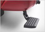 Rear bed step up
 Has anyone installed the TRD Air Filter in stock airbox?
 You Are Now Entering The Matrix
 Missing Jack and Spare kit
 Transfer Case Actuator Problems - Poll
Adding an Aux battery the best way
Discussion in '2.5 Gen Tundras (2014-2021)' started by thebuildist, May 12, 2024.


