

-
Welcome to Tundras.com!
You are currently viewing as a guest! To get full-access, you need to register for a FREE account.
As a registered member, you’ll be able to:- Participate in all Tundra discussion topics
- Transfer over your build thread from a different forum to this one
- Communicate privately with other Tundra owners from around the world
- Post your own photos in our Members Gallery
- Access all special features of the site
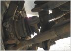 Need help with this problem
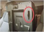 Console Organizer Tray
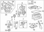 Replace drain bolt gasket for oil changes?
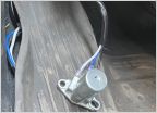 Footswitch Mount Ideas
 Thoughts on these please!
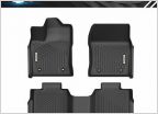 Floor mats!!!
DIY: 2007-2021 Tundra U-Joint and Carrier Bearing Replacement
Discussion in 'General Tundra Discussion' started by 300BLK, Jun 17, 2025.


