

-
Welcome to Tundras.com!
You are currently viewing as a guest! To get full-access, you need to register for a FREE account.
As a registered member, you’ll be able to:- Participate in all Tundra discussion topics
- Transfer over your build thread from a different forum to this one
- Communicate privately with other Tundra owners from around the world
- Post your own photos in our Members Gallery
- Access all special features of the site
 Loc’s Tundra Build
 TheTupper's Not-A-Build Thread
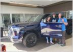 Exploring Cascadia - '22 1794 TRD-Offroad + Longbed
 2025 Ice Cap TRD Rally "Semi-Pro"
 BayAreaTruckin - '24 Platinum Hybrid
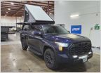 Sully: The Blurple Beast - Super Pacific Build
60centenergy's 2024 Lunar Rock SR5 TRD Sport
Discussion in '3rd Gen Builds (2022+)' started by 60centenergy, Aug 5, 2024.
Page 3 of 3
Page 3 of 3
Products Discussed in


