

-
Welcome to Tundras.com!
You are currently viewing as a guest! To get full-access, you need to register for a FREE account.
As a registered member, you’ll be able to:- Participate in all Tundra discussion topics
- Transfer over your build thread from a different forum to this one
- Communicate privately with other Tundra owners from around the world
- Post your own photos in our Members Gallery
- Access all special features of the site
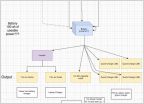 Auxiliary / Second "House Battery" in Bed - Help Needed
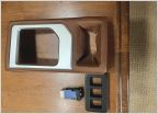 What are folks with Platinum and 1794s doing for extra switches?
 Dual Battery Charging
 Which gauge wire should I use?
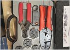 Wire crimpers....what do you use?
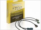 Head unit with SiriusXM
Custom CANbus Boost Gauges!
Discussion in 'Electrical' started by mitchspeaks, Dec 23, 2024.


