1. Welcome to Tundras.com!

    You are currently viewing as a guest! To get full-access, you need to register for a FREE account.

    As a registered member, you’ll be able to:
    • Participate in all Tundra discussion topics
    • Transfer over your build thread from a different forum to this one
    • Communicate privately with other Tundra owners from around the world
    • Post your own photos in our Members Gallery
    • Access all special features of the site

4WD Issue-- Tranfser case locks up when shifting from 4HI to 4LO

Discussion in '1st Gen Tundras (2000-2006)' started by seachunk2, Nov 4, 2023.

  1. Nov 4, 2023 at 10:25 AM
    #1
    seachunk2

    seachunk2 [OP] New Member

    Joined:
    Dec 5, 2018
    Member:
    #22625
    Messages:
    54
    Vehicle:
    2004 Tunda DC V6 4WD SR5 AT
    I've posted before regarding 4x4 issues on my 2004 Tundra SR5. I thought I had it all solved but not so.
    I have 4HI working great, so I am able to move to and from 2HI & 4HI without issue.
    However, when I am in 4HI and have a steady green light on the switch and instrument panel, then set the transmission to neutral while I am at idle, and select 4LO, both the 4HI and 4LO lights flash.
    At that point, I am unable to return back to 4Hi or 2HI. The front drive shaft is locked and I'm unable to get it to rotate.
    No matter what I do as far as pressing the 4HI or 4LO switches, both lights continue to flash. Even if I put the ignition switch to the off position and then turn it on, both lights continue to flash.
    If I disconnect the electrical connector plug from the ADD front actuator, the 4HI and 4LO flashing continues (green and amber colored lights).
    All the while this is occurring the front drive shaft is locked in.
    I have an old but working front actuator and even if I connect it for a test, the front drive shaft remains locked.
    The only way I am able to unlock the front drive shaft is by removing the cover to the transfer case actuator and manually pushing the shift rod to the 2Hi position (i.e. push inward in to the case as far as it will go- about 2-3/4" extruding from the transfer case housing edge).
    For now I just have 4HI and no 4LO.
    Question- can anyone tell me where the contacts within the ADD front actuator should be for the 2HI, 4HI and 2LO position pins (i.e on 3 pins on the outside face of the rotary gear)? I am assuming that the front actuator pins aren't in the correct timing position. I am unable to find anything online that shows the contact position relative to the tracks on the inside of the actuator cap. I'm hoping if I set it correctly, I'll get 4LO to work. I've tried countless times without success. All I am able to do is get 4HI working.
    I also checked both 4HI and the 4LO switches on the transfer case actuator and both are open or closed when they should be depending on what shift position is selected. I'm pretty sure the transfer case actuator is correctly timed and the circuits track within the cap are all in excellent condition. I also traced each wire on the entire 4x4 system to confirm all the wiring is in tack.
    I went point to point of each circuit between both actuators (including the 2 transfer case switches) and the 4x4 ECU located behind the front passenger side panel. All traced wires show continuity from point to point. I replaced the small wire harness that connects to the ADD front actuator with a brand new one I bought from Toyota.
    I was able to find information that tells me the 2HI, 4Hi and 4LO positions for the transfer case actuator but no luck finding similar information for the front actuator. I have the Tundra factory service manual but I am not finding an ADD contact position diagram but it does have the schematic so I may need to trace the wiring again if I need to.
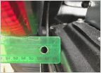
    I noticed the is a slight bump in the metal housing of the ADD actuator at about 1 o'clock location. I'm assuming the bump is there for aligning the rotary gear when the actuator is being assembled at the factory. I believe the 3 contact pins on the internal rotary gear line up with this bump but I am not certain. I attached a picture on the metal housing so you can see the "bump" I am referring to. The blue arrow is pointing to the bump. I also posted a picture of the inside of the ADD front differential actuator cap. If anyone knows where the 2HI, 4HI and 4LO positions are, it will really help me out.
    One more piece of information....I've been lining up the 3 pins in line with the metal housing bump (in the attached picture the 3 pins are at the 5 o'clock position but when I am assemling, they are at about 1 o'clock and in line with the bump). Once I have the pins in line, I place the cover over the rotary gear but just slightly clockwise of the screw holes on the metal housing. I then rotate the cap counter-clockwise (ccw) and install the 4 cover screws when its lined up with the metal housing holes. As I rotate ccw, I feel a slight amount of spring tension. Here again I'm assuming that tension is correct because I noticed it was there when I first removed the cover. I felt the cap wanting to release the spring tension by rotating itself clock wise when the last screws was removed.

    Front ADD Cover.jpg

    Front ADD Metal.jpg
     
    Last edited: Nov 4, 2023
  2. Nov 4, 2023 at 10:38 AM
    #2
    Jack McCarthy

    Jack McCarthy Working remotely from the local pub

    Joined:
    Nov 2, 2020
    Member:
    #54409
    Messages:
    10,277
    Gender:
    Male
    First Name:
    Bill
    North of Boston
    Vehicle:
    02 Tundra AC SR5 V8 4x4
    Sounds like a very specific question a Toyota tech could answer. We have a general forum area where a tech may be able to answer if he has time. Just a suggestion in case nobody else here a has a good answer to this question.

    Here’s the link…
    https://www.tundras.com/threads/ask-the-toyota-mechanic.2404/
     

Products Discussed in

To Top