-
Welcome to Tundras.com!
You are currently viewing as a guest! To get full-access, you need to register for a FREE account.
As a registered member, you’ll be able to:- Participate in all Tundra discussion topics
- Transfer over your build thread from a different forum to this one
- Communicate privately with other Tundra owners from around the world
- Post your own photos in our Members Gallery
- Access all special features of the site
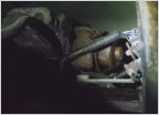 Fuel leak 09 Tundra
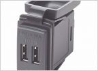 Adding usb in 07
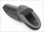 Antenna delete plate
 Battery/Charging System Issue?
 Front Driver Door Speaker Stopped Working
 Big Brake Kits
Half of fuse box not working!
Discussion in '2nd Gen Tundras (2007-2013)' started by lmobeats, Mar 21, 2025.
Page 1 of 2
Page 1 of 2