

-
Welcome to Tundras.com!
You are currently viewing as a guest! To get full-access, you need to register for a FREE account.
As a registered member, you’ll be able to:- Participate in all Tundra discussion topics
- Transfer over your build thread from a different forum to this one
- Communicate privately with other Tundra owners from around the world
- Post your own photos in our Members Gallery
- Access all special features of the site
 Fuel Pump ECU Connector Terminal Size
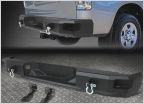 Rear bumper was hit in parking lot. Replacement bumper ideas?
 Spongey brakes
 Couple of questions for you guys
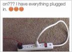 How to put electric plug into bumper
 Under rear seat sub box
How to Swap 2.5gen steering wheel to 2nd gen
Discussion in '2nd Gen Tundras (2007-2013)' started by chrisf111, May 26, 2022.
Page 1 of 2
Page 1 of 2


