

-
Welcome to Tundras.com!
You are currently viewing as a guest! To get full-access, you need to register for a FREE account.
As a registered member, you’ll be able to:- Participate in all Tundra discussion topics
- Transfer over your build thread from a different forum to this one
- Communicate privately with other Tundra owners from around the world
- Post your own photos in our Members Gallery
- Access all special features of the site
 Land cruiser 200 series snorkel
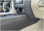 Question about an interior loose screw on my lower-front console box (link and pics)
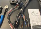 Need trailer harness part numbers
 Headlight bulbs
Drive Monitor Wiring - MPG
Discussion in '2nd Gen Tundras (2007-2013)' started by Kaner, Apr 29, 2021.
Page 1 of 2
Page 1 of 2
